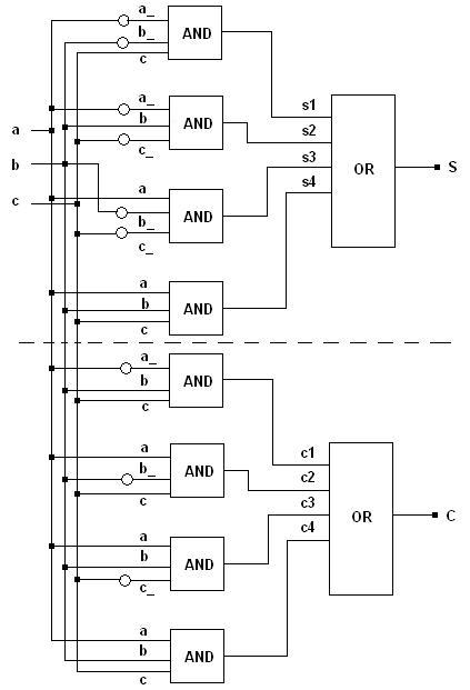
Let a and b be input signals to a 1-bit full-adder, and c the carry input. Let S be the sum output, and C the carry output. Then, the truth table for S and C, and the corresponding logic diagram, are shown below.
a  |  b  |  c  |      S  |  C
---|-----|-----|---------|----
0  |  0  |  0  |      0  |  0
---|-----|-----|---------|----
0  |  0  |  1  |      1  |  0
---|-----|-----|---------|----
0  |  1  |  0  |      1  |  0
---|-----|-----|---------|----
0  |  1  |  1  |      0  |  1
---|-----|-----|---------|----
1  |  0  |  0  |      1  |  0
---|-----|-----|---------|----
1  |  0  |  1  |      0  |  1
---|-----|-----|---------|----
1  |  1  |  0  |      0  |  1
---|-----|-----|---------|----
1  |  1  |  1  |      1  |  1

 #include <lcs/or.h>
 #include <lcs/and.h>
 #include <lcs/not.h>
 #include <lcs/tester.h>

// All classes of the libLCS are defined in the namespace lcs.
using namespace lcs;

int main(void)
{
    // Creating a single line bus for each 'node' in the above circuit.
    // Note that Bus is a class template from which a single line class Bus<1>
    // is being initialised using the default template parameter. The
    // busses a_, b_ and c_ each denote the busses at the outputs of the
    // NOT gates of the corresponding input data busses.
    Bus<> a, b, c, a_, b_, c_, S, C, s1, s2, s3, s4, c1, c2, c3, c4;

    // Initialising NOT gates which obtain the inverses of the input busses.
    Not n1(a_, a), n2(b_, b), n3(c_, c);

    // Initialising an AND gate for each of the 4 min-terms involved. Each
    // AND should take 3 input data lines. Hence, the class And<3> is used.
    // Moreover, the input busses to these AND gates should have 3 lines each.
    // Hence, the 3 line input busses are generated using the overloaded
    // '*' operator. The '*' does not denote a multiplication (or a logical AND),
    // but is a bus/line concatenation operator. It concatenates two busses
    // to produce another bus which contains lines from both the operand busses.
    And<3> sa1(s1, a_*b_*c), sa2(s2, a_*b*c_), sa3(s3, a*b_*c_), sa4(s4, a*b*c);
    And<3> ca1(c1, a_*b*c), ca2(c2, a*b_*c), ca3(c3, a*b*c_), ca4(c4, a*b*c);

    // The 4 input OR gates which take the outputs of the AND gates and produce the
    // desired results.
    Or<4> so(S, s1*s2*s3*s4), co(C, c1*c2*c3*c4);

    // A tester object which takes a 3 line input bus and a 2 line output bus.
    // The 3 line input bus is generated as c*b*a and not as a*b*c as the
    // concatenation operator concatenates the lines from the right operand (of
    // the operator '*') into the MSB bits of the resultant bus object. The
    // ouput bus is generated as C*S for the same reason.
    Tester<3, 2> tester(c*b*a, C*S);

    // Running the tester object. The lcs::Tester::run function feeds all possible
    // combinations to the input bus and obtains the result from the output bus.
    // The result is displayed in a tabulated format on the stdout device.
    tester.run();

    return 0;
}
Back to all examples
 1.4.7
1.4.7