|
- A Logic Circuit Simulation Library in C++ |

|
- A Logic Circuit Simulation Library in C++ |
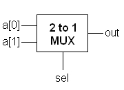
The aim of this example it build and simulate a 2-to-1 multiplexer using continuous assignments where the assignment expression has bit-selects. The block diagram of the circuit we intend to build is as follows.

The the boolean function for out is:
out = a[0]'.a[1].sel + a[0].a[1]'.sel' + a[0].a[1].sel' + a[0].a[1].sel
The code to implement the above logic equation is as follows.
#include <lcs/bus.h>
#include <lcs/tester.h>
#include <lcs/simul.h>
#include <lcs/changeMonitor.h>

using namespace lcs;

int main(void)
{
    Bus<1> sel, out;
    Bus<2> a;

    out.cass<0>(~a[0]&a[1]&sel | a[0]&~a[1]&~sel | a[0]&a[1]&~sel | a[0]&a[1]&sel);

    ChangeMonitor<2> inputMonitor(a, "Input", DUMP_ON);
    ChangeMonitor<1> selectMonitor(sel, "Select", DUMP_ON);
    ChangeMonitor<1> outputMonitor(out, "Output", DUMP_ON);

    Tester<3> tester((a,sel));

    Simulation::setStopTime(1000);
    Simulation::start();

    return 0;
}
The output when the above program is compiled and run is as below. See this for information on interpreting the output.
At time: 0,     Input: 00
At time: 0,     Select: 0
At time: 0,     Output: 0
At time: 200,   Input: 01
At time: 200,   Output: 1
At time: 300,   Input: 10
At time: 300,   Output: 0
At time: 400,   Input: 11
At time: 400,   Output: 1
At time: 500,   Input: 00
At time: 500,   Select: 1
At time: 500,   Output: 0
At time: 600,   Input: 01
At time: 700,   Input: 10
At time: 700,   Output: 1
At time: 800,   Input: 11
Below is the screenshot of the gtkwave plot of the generated VCD file.

